ELECTRIC ENERGY SAVING DEVICE
Technical Field
The present invention relates to an electric energy saving device, and more particularly, to an electric energy saving device connected to an electricity line for supplying electric power, in which a ceramic layer is coated on an inner surface of a housing and an inner cover plate is placed in a space defined in the housing to absorb and emit rotating electromagnetic waves emanated from the ceramic layer and thereby render a resonance absorption state, so that rotating electromagnetic waves generated in the electric energy saving device is supplied to the electricity line in such a way as to decrease electric power consumption and save electric energy.
Background Art
Generally, a far infrared ray serves as a kind of electromagnetic wave and has a wavelength of 2.5 - 1,000 micrometers. The far infrared ray having a wavelength of 2.5 - 30 micrometers is mainly used in an industrial field. The far infrared ray has various characteristics including a resonance absorption function, emission, and deep reaching force. Usually, molecules constituting a substance implement their inherent angle-changing vibration, rotating vibration and contracting vibration, depending upon an arrangement of atoms. A frequency representing a vibration wavelength of molecules is determined as a specified value, relying upon a molecular structure, generally of 2.5-30 micrometers. At this time, when a far infrared ray is irradiated onto an object, if a vibration frequency of radiant energy and a vibration frequency of the molecules correspond to each other, the molecules absorb the far infrared radiant energy to be intensified in its vibration, which is called the resonance absorption function. Due to this resonance absorption function, a pm1 of kinetic energy is changed into activation energy to further activate molecular motion.
The emission means that far infrared rays released from an object is transferred as heat. The deep reaching force means that penetration force is determined in proportion to a square root of a wavelength of irradiated radiant energy and thus a far infrared ray of a short wavelength is decreased in its penetration force in comparison with a far infrared ray of a long wavelength.
Recently, using the above-described characteristics, a far infrared ray is employed in a diversity of uses. As being most commercialized, ceramics emitting far infrared rays are employed in a heating device or a sauna bath. In particular, the far infrared rays emitted from the ceramics deeply penetrate into the human body to activate molecules or atoms, discharge waste matters and promote metabolism, and thereby, the human body can be restored to a healthy condition. Besides, far infrared rays provide a wide range of effectiveness. However, there is no case in which far infrared rays are used to save electric energy.
Disclosure of the Invention
Accordingly, the present invention has been made in an effort to solve the problems occurring in the related art, and an object of the present invention is to provide an electric energy saving device which is constructed to decrease electric power consumption using far infrared rays.
In order to achieve the above object, the device of the present invention is constructed in a manner such that, when far infrared rays of a specified wavelength band are supplied to an electricity line through which a current flows, molecules constituting a conductor of the electricity line absorb the far infrared rays to cause resonance absorption vibration and to thereby be activated in their motion. That is to say, in the present invention, a space for supplying, as thermodynamic activation energy, rotating electromagnetic waves which are also called IT-rays or Gibbs free energy, is defined in the conductor forming the electricity line.
The device according to the present invention includes a ceramic layer for generating rotating electromagnetic waves in the space, conductive plates serving as conductor bodies placed in a predetermined space to collect the rotating electromagnetic waves generated in the ceramic layer, and an electricity line connected to the conductor bodies to discharge the rotating electromagnetic waves collected by the conductive plates. Consequently, as a resistance of the conductor is decreased by virtue of the activation energy discharged through the electricity line, current consumption is reduced and it is possible to save electric energy.
According to the present invention, there is provided an electric energy saving device comprising: a housing made of metal or plastic and coated on an inner surface thereof with a ceramic layer mainly formed of silicate to emanate rotating electromagnetic waves, so that wave transfer to the outside is prevented; an inner cover plate supported in a space defined in the housing by separation maintaining rods, to repeatedly absorb and emit rotating electromagnetic waves emanated from the ceramic layer and thereby perform a resonance absorption function; conductive plates rested on supp0l1ing insulation blocks so that rotating electromagnetic waves generated in a free space defined between the inner cover plate and a bottom surface of the housing can penetrate into the conductive plates; and a wire for outputting, out of the housing, the rotating electromagnetic waves penetrated into the conductive plates, to an electricity line.
Technical principles of the present invention will be concretely described below.
(i) Generation of TI-rays
In the formation of rotating electromagnetic waves, that is, O-rays according to a theoretical background of the present invention, when observing an atomic binding structure of ceramic serving as a far infrared ray radiating body, covalent bonding and crystallization pi bonding arc combined with each other. In this state, as an alternating magnetic field is created, rotating electromagnetic waves arc generated. Further, heat energy introduced from the outside is also converted into rotating electromagnetic waves. Moreover, in the case of coating ceramic powder on a metal plate, an increased amount of rotating electromagnetic waves are generated at a boundary layer between crystal bonding of the metal plate and covalent bonding of the ceramic.
In a basic technical theory of the present invention, the above described principle is applied to a structure of a far infrared ray radiating body so that the radiating body can generate and supply by itself the rotating electromagnetic energy.
(ii) radiation and absorption of far infrared rays and relationship with rotating electromagnetic waves
Diverse structures of molecules constituting each substance have their specified vibration patterns and rotation frequencies depending upon differences of conglomerated scheme, arrangement and conglomerating force in mass structures of their atoms. When far infrared rays are radiated toward a substance, if a vibration frequency of radiant energy and a molecular vibration frequency of the substance correspond to each other, the molecules absorb the energy of the far infrared rays to be intensified in their molecular motion.
This is called a resonance absorption function. More concretely describing, rotating electromagnetic waves emanated from a ceramic-coated surface are changed into far infrared rays (having maximum radiation energy approaching to 8-11 micrometers) in a free space, due to a basic feature of the free space. As the far infrared rays are emitted from one surface and absorbed by other surfaces, the far infrared rays are changed again into rotating electromagnetic waves due to the presence of alternating magnetic fields.
(iii) Absorption of rotating electromagnetic waves and electric energy saving principle.
The existing energy is represented by energy of electrons flowing through a conductive wire. According to recent researches, it was found that electric energy is composed of flow of rotating electromagnetic waves and vibration of electrons. Based on this fact, it is judged that an electricity line can absorb rotating electromagnetic waves, and when an energy passage line of a far infrared ray radiating body is brought into contact with the electricity line, due to the flow of the rotating electromagnetic waves inside the electricity line, absorption force is produced by a static pressure difference between the far infrared ray radiating body and the electricity line. Due to this absorption force, the rotating electromagnetic waves generated in the far infrared ray radiating body are moved into the electricity line.
Then, describing a relationship between the absorption force and saving of electric power, the rotating electromagnetic waves absorbed into the electricity line create new crystal bonding of atoms in the electricity line, and accordingly, a new alternating magnetic field changes heat energy which is being lost due to the existing electric resistance in the electricity line, again into rotating electromagnetic waves in the form of effective energy. The rotating electromagnetic waves resultantly play an important role of reducing a various types of resistances in the electricity line, thereby rendering electric energy saving effect of about 5-15%.
Describing a adaptation period of the far infrared ray radiating body and the role of the rotating electromagnetic waves, while the rotating electromagnetic waves absorbed into the electricity line form crystal bonding in fine structures of the conductive wire, as the rotating electromagnetic waves arc continuously supplied, the crystal bonding is broken again. Since covalent bonding cannot allow current flow, only crystal bonding protected by the covalent bonding is finally left, whereby a electric energy saving function is stabilized.
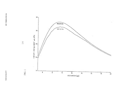
A variety of conventionally used radiating materials can be employed is as the flu' infrared ray radiating bodies for generating far infrared rays of desired wavelength bands. Specifically, naturally obtained far infrared ray radiating materials can be employed in the conventionally powdered or baked and powdered state. Preferably, silicates or quartz porphyry generally obtained in a mine can be effectively employed in a powdered-as-it-is state or as baked and powdered ceramic. Results obtained by measuring radiant energy of silicate by wavelengths are given in FIG. I. As can be readily seen from FIG. I, since the silicate has a maximum wavelength of 8-11 micrometer, it can he employed as an appropriate radiating body in the present invention.
A far infrared ray radiating body can be employed in a state wherein it is formed to have a diversity of shapes as occasion demands. In one example, after a far infrared ray radiating material is coated on a surface of a plastic or metal plate into a thickness of no less than 1 mm, the plate can be formed into the shape of a box to be actually employed. Generally, if heat is applied to a far infrared ray radiating body, an amount of infrared ray radiating energy is abruptly increased, and a radiated wavelength is gradually moved toward a short wavelength. Hence, in the case of heating the far infrared radiating body according to the present invention within a predetermined temperature range, as an amount of infrared ray radiating energy IS increased, activation energy of a conductor constituting the electricity line can be increased. However, if a temperature is excessively raised, a wavelength goes beyond the one desired in the present invention, which is not preferable. It is preferred that a heating temperature is maintained within the range of no greater than 150°C.
In order to sufficiently accomplish electric energy saving effect through radiation of far infrared rays, a position where far infrared rays are supplied to the electricity line is regarded important. In this connection, it is preferred that an increased amount of far infrared rays are supplied to a portion of an electricity line which is positioned directly behind a transformer for transforming a supplying voltage in an exterior wiring and a load which consumes a great amount of electric energy.
In a most simple way, electric signals are allowed to be introduced into the far infrared ray radiating bodies so as to supply far infrared rays to the electricity line.
In another way, far infrared rays can be supplied to the electricity line employing another transferring medium. In other words, after a transferring medium having the same conductor as the electricity line is introduced into the far infrared ray radiating bodies, the medium can be connected to the electricity line in a conducted state or a non-conducted state so as to supply far infrared rays to the electricity line.
In the case of supplying far infrared rays to the electricity line as described above, after a function adjustment period of three months is lapsed, it is possible to stably obtain electric energy saving effect.
Brief Description of the Drawings
The above objects, and other features and advantages of the present invention will become more apparent after a reading of the following detailed description when taken in conjunction with the drawings, in which:
FIG. 1 is a graph showing a level of energy emanated from the conventional ceramic layer, depending upon a wavelength;
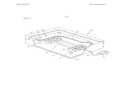
FIG. 2 is a partially broken-away perspective view illustrating a construction of an electric energy saving device in accordance with an embodiment of the present invention;
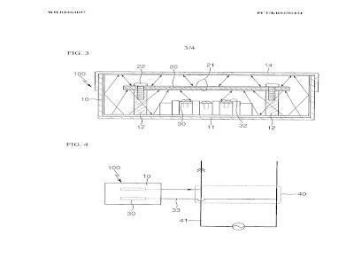
FIG. 3 is a cross-sectional view of the electric energy saving device according to the present invention;
FIG. 4 is an explanatory view illustrating an in-use state of the electric energy saving device according to the present invention; and
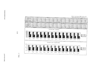
FIG. 5 shows results of tests implemented for the electric energy saving device according to the present invention.
Best Mode for Carrying Out the Invention
Reference will now be made in greater detail to a preferred embodiment of the invention, an example of which is illustrated in the accompanying drawings. Wherever possible, the same reference numerals will be used throughout the drawings and the description to refer to the same or like parts.
FIG. 2 is a partially broken-away perspective view illustrating a construction of an electric energy saving device in accordance with an embodiment of the present invention; and FIG. 3 is a cross-sectional view of the electric energy saving device according to the present invention. An electric energy saving device 100 according to the present invention includes a housing 10. The housing 10 is made of metal or plastic and coated on an inner surface thereof with a ceramic layer 11 (preferably, having a thickness of I mm) mainly formed of silicate to emanate rotating electromagnetic waves, so that wave transfer to the outside is prevented. An inner cover plate 20 is supported in a space defined in the housing 10 by separation maintaining rods 12. Conductive plates 30 are rested on supporting insulation blocks 31 so that rotating electromagnetic waves generated in a free space defined between the inner cover plate 20 and a bottom surface of the housing 10 can penetrate into the conductive plates 30. The conductive plates 30 are connected with a wire 33 which in turn is connected to an electricity line.
It is preferred that the inner cover plate 20 has a size for ensuring that a predetermined space is defined between side walls of the housing 10 and the inner cover plate 20. A height of the supporting insulation blocks 31 is adjusted in a manner such that the inner cover plate 20 is positioned at the middle in the housing 10. The reference numeral 21 represents covering ceramic layers, 22 screws for coupling the inner cover plates 20 to the separation maintaining rods 12, 32 screws for coupling the conductive plates 30 to the supporting insulation blocks 31, and 34 a plug to be connected with the electricity line through a socket.
In the present invention constructed as mentioned above, after or before assembling the electric energy saving device 100 as shown in FIG. 2, the ceramic layer 11 is heated. At this time, it is preferred to momentarily heat the ceramic layer 11 within a temperature range of 100-IS0aC while not causing deformation of the housing 10. The reason for this is that, if the temperature exceeds 15O0C, the housing 10 is likely to be deformed, and if the temperature is less than 100°C, activation of the ceramic layer 11 is retarded to deteriorate generation of rotating electromagnetic waves. Then, as covalent bonding and the crystallization pi bonding of the ceramic layer 11 by it self are activated by the heating, alternating magnetic fields and rotating electromagnetic waves are created and generated.
The rotating electromagnetic waves are generated in the housing 10 to have numerous wavelengths, as can be readily seen from FIG. 3. The rotating electromagnetic waves give rise to a resonance absorption function via the inner cover plate 20. Therefore, by the fact that the inner cover plate 20 made of a metallic material is coated on upper and lower surfaces thereof with the covering ceramic layers 21, an increased amount of rotating electromagnetic waves are generated at. a boundary layer between crystal bonding of the metal plate and covalent bonding of the ceramic, which acts as a factor of explosively increasing generation of rotating electromagnetic waves. Namely, the rotating electromagnetic waves emanated from the surface of the coated surface of the ceramic layer 11 are repeatedly reflected and absorbed in a free space by the covering ceramic layers 21 of the inner cover plate 20, whereby conversion from the alternating magnetic fields to the rotating electromagnetic waves continuously occurs. In this case, because the inner cover plate 20 has a size for ensuring that a predetermined space is defined between the side walls of the housing 10 and the inner cover plate 20, the rotating electromagnetic waves function to continuously emanate kinetic energy to thereby be repeatedly absorbed on the upper and lower surfaces of the inner cover plate 20. Further, because the supporting insulation blocks 31 are determined in their height in a manner such that the conductive plates 30 are positioned at the middle between the bottom surface of the housing 10 and the inner cover plate 20, an amount of rotating electromagnetic waves guided toward and absorbed by the conductive plates 30 can be maximized.
Due to the fact that the rotating electromagnetic waves are most activated in the free space between the inner cover plate 20 and the bottom surface of the housing 10, they arc guided toward the conductive plates 30 positioned in the free space. As shown in FIG. 4, the conductive plates 30 are connected with an end terminal of a conventional socket 40 for supplying electric power. While the electricity line 41 connected with the end terminal has its own now of rotating electromagnetic waves, because an intensity of the rotating electromagnetic waves generated in the housing 10 of the electric energy saving device is relatively small, by fixing the plug 34 connected with the conductive plates 30 via the wire 33 into the socket 40 as shown in FIG. 4, the rotating electromagnetic waves generated in the housing 10 is absorbed into the electricity line 41. At this time, absorption force is produced by a static pressure difference existing between the electric energy saving device 100 and the power supplying electricity line 41. Due to the absorption force, the rotating electromagnetic waves generated in the electric energy saving device 100 are continuously moved into the electricity line 41.
The rotating electromagnetic waves absorbed into the electricity line 41 create new crystal bonding of atoms in the conductive wire. Accordingly, the alternating magnetic fields converts heat energy which is otherwise lost due to an electric resistance existing in the conductive line, into rotating electromagnetic energy to transform it into effective electric energy.
The rotating electromagnetic energy resultantly plays an important role of decreasing a variety of resistances existing in the conductive wire. The decrease in resistance causes a decrease in current, whereby, as a resistance loss is reduced, a desired output can be accomplished with reduced current flow. Considering an equation, P = I x V x case, since a voltage V is constant, if a current I is reduced, an amount of consumed electric energy P can be reduced.
As can be readily seen from FIG. 5, the above-described reduction in electric power consumption and current was confirmed by performing tests a multitude of times using a System VIP 3 Energy Analyzer made in Italy.
Industrial Applicability
As apparent from the above description, the electric energy saving device according to the present invention provides advantages as described below.
In the present invention, a space for supplying, as thermodynamic activation energy, rotating electromagnetic waves which are also called IT- rays or Gibbs free energy, is defined in a conductor constituting an electricity line, and the device includes a ceramic layer for generating rotating electromagnetic waves in a space, conductive plates serving as conductor bodies placed in a predetermined space to collect the rotating electromagnetic waves generated in the ceramic layer, and the electricity line connected to the conductor bodies to discharge the rotating electromagnetic waves collected by the conductive plates. Consequently, as a resistance of the conductor is decreased by virtue of the activation energy discharged through the electricity line, current consumption is reduced and it is possible to save electric energy. By applying the present invention for a predetermined period of time, significant electric energy saving effect of no less than 15% can be accomplished.
In the drawings and specification, there have been disclosed typical preferred embodiments of the invention and, although specific terms are employed, they are used in a generic and descriptive sense only and not for purposes of limitation, the scope of the invention being set forth in the following claims.
Claims
1. An electric energy saving device comprising:
a housing made of metal or plastic and coated on an inner surface thereof with a ceramic layer mainly formed of silicate to emanate rotating electromagnetic waves, so that wave transfer to the outside is prevented;
an inner cover plate supported in a space defined in the housing by separation maintaining rods, to repeatedly absorb and emit rotating electromagnetic waves emanated from the ceramic layer and thereby perform a resonance absorption function;
conductive plates rested on supporting insulation blocks so that rotating electromagnetic waves generated in a free space defined between the inner cover plate and a bottom surface of the housing can penetrate into the conductive plates; and
a wire for outputting, out of the housing, the rotating electromagnetic waves penetrated into the conductive plates, to an electricity line.
2. The electric energy saving device as set forth in claim I, wherein the inner cover plate has a size for ensuring that a predetermined space is defined between side walls of the housing and the inner cover plate.
3. The electric energy saving device as set forth in claim I, wherein the ceramic layer is heated to a temperature of no greater than 150°C.
Technical Field
The present invention relates to an electric energy saving device, and more particularly, to an electric energy saving device connected to an electricity line for supplying electric power, in which a ceramic layer is coated on an inner surface of a housing and an inner cover plate is placed in a space defined in the housing to absorb and emit rotating electromagnetic waves emanated from the ceramic layer and thereby render a resonance absorption state, so that rotating electromagnetic waves generated in the electric energy saving device is supplied to the electricity line in such a way as to decrease electric power consumption and save electric energy.
Background Art
Generally, a far infrared ray serves as a kind of electromagnetic wave and has a wavelength of 2.5 - 1,000 micrometers. The far infrared ray having a wavelength of 2.5 - 30 micrometers is mainly used in an industrial field. The far infrared ray has various characteristics including a resonance absorption function, emission, and deep reaching force. Usually, molecules constituting a substance implement their inherent angle-changing vibration, rotating vibration and contracting vibration, depending upon an arrangement of atoms. A frequency representing a vibration wavelength of molecules is determined as a specified value, relying upon a molecular structure, generally of 2.5-30 micrometers. At this time, when a far infrared ray is irradiated onto an object, if a vibration frequency of radiant energy and a vibration frequency of the molecules correspond to each other, the molecules absorb the far infrared radiant energy to be intensified in its vibration, which is called the resonance absorption function. Due to this resonance absorption function, a pm1 of kinetic energy is changed into activation energy to further activate molecular motion.
The emission means that far infrared rays released from an object is transferred as heat. The deep reaching force means that penetration force is determined in proportion to a square root of a wavelength of irradiated radiant energy and thus a far infrared ray of a short wavelength is decreased in its penetration force in comparison with a far infrared ray of a long wavelength.
Recently, using the above-described characteristics, a far infrared ray is employed in a diversity of uses. As being most commercialized, ceramics emitting far infrared rays are employed in a heating device or a sauna bath. In particular, the far infrared rays emitted from the ceramics deeply penetrate into the human body to activate molecules or atoms, discharge waste matters and promote metabolism, and thereby, the human body can be restored to a healthy condition. Besides, far infrared rays provide a wide range of effectiveness. However, there is no case in which far infrared rays are used to save electric energy.
Disclosure of the Invention
Accordingly, the present invention has been made in an effort to solve the problems occurring in the related art, and an object of the present invention is to provide an electric energy saving device which is constructed to decrease electric power consumption using far infrared rays.
In order to achieve the above object, the device of the present invention is constructed in a manner such that, when far infrared rays of a specified wavelength band are supplied to an electricity line through which a current flows, molecules constituting a conductor of the electricity line absorb the far infrared rays to cause resonance absorption vibration and to thereby be activated in their motion. That is to say, in the present invention, a space for supplying, as thermodynamic activation energy, rotating electromagnetic waves which are also called IT-rays or Gibbs free energy, is defined in the conductor forming the electricity line.
The device according to the present invention includes a ceramic layer for generating rotating electromagnetic waves in the space, conductive plates serving as conductor bodies placed in a predetermined space to collect the rotating electromagnetic waves generated in the ceramic layer, and an electricity line connected to the conductor bodies to discharge the rotating electromagnetic waves collected by the conductive plates. Consequently, as a resistance of the conductor is decreased by virtue of the activation energy discharged through the electricity line, current consumption is reduced and it is possible to save electric energy.
According to the present invention, there is provided an electric energy saving device comprising: a housing made of metal or plastic and coated on an inner surface thereof with a ceramic layer mainly formed of silicate to emanate rotating electromagnetic waves, so that wave transfer to the outside is prevented; an inner cover plate supported in a space defined in the housing by separation maintaining rods, to repeatedly absorb and emit rotating electromagnetic waves emanated from the ceramic layer and thereby perform a resonance absorption function; conductive plates rested on supp0l1ing insulation blocks so that rotating electromagnetic waves generated in a free space defined between the inner cover plate and a bottom surface of the housing can penetrate into the conductive plates; and a wire for outputting, out of the housing, the rotating electromagnetic waves penetrated into the conductive plates, to an electricity line.
Technical principles of the present invention will be concretely described below.
(i) Generation of TI-rays
In the formation of rotating electromagnetic waves, that is, O-rays according to a theoretical background of the present invention, when observing an atomic binding structure of ceramic serving as a far infrared ray radiating body, covalent bonding and crystallization pi bonding arc combined with each other. In this state, as an alternating magnetic field is created, rotating electromagnetic waves arc generated. Further, heat energy introduced from the outside is also converted into rotating electromagnetic waves. Moreover, in the case of coating ceramic powder on a metal plate, an increased amount of rotating electromagnetic waves are generated at a boundary layer between crystal bonding of the metal plate and covalent bonding of the ceramic.
In a basic technical theory of the present invention, the above described principle is applied to a structure of a far infrared ray radiating body so that the radiating body can generate and supply by itself the rotating electromagnetic energy.
(ii) radiation and absorption of far infrared rays and relationship with rotating electromagnetic waves
Diverse structures of molecules constituting each substance have their specified vibration patterns and rotation frequencies depending upon differences of conglomerated scheme, arrangement and conglomerating force in mass structures of their atoms. When far infrared rays are radiated toward a substance, if a vibration frequency of radiant energy and a molecular vibration frequency of the substance correspond to each other, the molecules absorb the energy of the far infrared rays to be intensified in their molecular motion.
This is called a resonance absorption function. More concretely describing, rotating electromagnetic waves emanated from a ceramic-coated surface are changed into far infrared rays (having maximum radiation energy approaching to 8-11 micrometers) in a free space, due to a basic feature of the free space. As the far infrared rays are emitted from one surface and absorbed by other surfaces, the far infrared rays are changed again into rotating electromagnetic waves due to the presence of alternating magnetic fields.
(iii) Absorption of rotating electromagnetic waves and electric energy saving principle.
The existing energy is represented by energy of electrons flowing through a conductive wire. According to recent researches, it was found that electric energy is composed of flow of rotating electromagnetic waves and vibration of electrons. Based on this fact, it is judged that an electricity line can absorb rotating electromagnetic waves, and when an energy passage line of a far infrared ray radiating body is brought into contact with the electricity line, due to the flow of the rotating electromagnetic waves inside the electricity line, absorption force is produced by a static pressure difference between the far infrared ray radiating body and the electricity line. Due to this absorption force, the rotating electromagnetic waves generated in the far infrared ray radiating body are moved into the electricity line.
Then, describing a relationship between the absorption force and saving of electric power, the rotating electromagnetic waves absorbed into the electricity line create new crystal bonding of atoms in the electricity line, and accordingly, a new alternating magnetic field changes heat energy which is being lost due to the existing electric resistance in the electricity line, again into rotating electromagnetic waves in the form of effective energy. The rotating electromagnetic waves resultantly play an important role of reducing a various types of resistances in the electricity line, thereby rendering electric energy saving effect of about 5-15%.
Describing a adaptation period of the far infrared ray radiating body and the role of the rotating electromagnetic waves, while the rotating electromagnetic waves absorbed into the electricity line form crystal bonding in fine structures of the conductive wire, as the rotating electromagnetic waves arc continuously supplied, the crystal bonding is broken again. Since covalent bonding cannot allow current flow, only crystal bonding protected by the covalent bonding is finally left, whereby a electric energy saving function is stabilized.
A variety of conventionally used radiating materials can be employed is as the flu' infrared ray radiating bodies for generating far infrared rays of desired wavelength bands. Specifically, naturally obtained far infrared ray radiating materials can be employed in the conventionally powdered or baked and powdered state. Preferably, silicates or quartz porphyry generally obtained in a mine can be effectively employed in a powdered-as-it-is state or as baked and powdered ceramic. Results obtained by measuring radiant energy of silicate by wavelengths are given in FIG. I. As can be readily seen from FIG. I, since the silicate has a maximum wavelength of 8-11 micrometer, it can he employed as an appropriate radiating body in the present invention.
A far infrared ray radiating body can be employed in a state wherein it is formed to have a diversity of shapes as occasion demands. In one example, after a far infrared ray radiating material is coated on a surface of a plastic or metal plate into a thickness of no less than 1 mm, the plate can be formed into the shape of a box to be actually employed. Generally, if heat is applied to a far infrared ray radiating body, an amount of infrared ray radiating energy is abruptly increased, and a radiated wavelength is gradually moved toward a short wavelength. Hence, in the case of heating the far infrared radiating body according to the present invention within a predetermined temperature range, as an amount of infrared ray radiating energy IS increased, activation energy of a conductor constituting the electricity line can be increased. However, if a temperature is excessively raised, a wavelength goes beyond the one desired in the present invention, which is not preferable. It is preferred that a heating temperature is maintained within the range of no greater than 150°C.
In order to sufficiently accomplish electric energy saving effect through radiation of far infrared rays, a position where far infrared rays are supplied to the electricity line is regarded important. In this connection, it is preferred that an increased amount of far infrared rays are supplied to a portion of an electricity line which is positioned directly behind a transformer for transforming a supplying voltage in an exterior wiring and a load which consumes a great amount of electric energy.
In a most simple way, electric signals are allowed to be introduced into the far infrared ray radiating bodies so as to supply far infrared rays to the electricity line.
In another way, far infrared rays can be supplied to the electricity line employing another transferring medium. In other words, after a transferring medium having the same conductor as the electricity line is introduced into the far infrared ray radiating bodies, the medium can be connected to the electricity line in a conducted state or a non-conducted state so as to supply far infrared rays to the electricity line.
In the case of supplying far infrared rays to the electricity line as described above, after a function adjustment period of three months is lapsed, it is possible to stably obtain electric energy saving effect.
Brief Description of the Drawings
The above objects, and other features and advantages of the present invention will become more apparent after a reading of the following detailed description when taken in conjunction with the drawings, in which:
FIG. 1 is a graph showing a level of energy emanated from the conventional ceramic layer, depending upon a wavelength;
FIG. 2 is a partially broken-away perspective view illustrating a construction of an electric energy saving device in accordance with an embodiment of the present invention;
FIG. 3 is a cross-sectional view of the electric energy saving device according to the present invention;
FIG. 4 is an explanatory view illustrating an in-use state of the electric energy saving device according to the present invention; and
FIG. 5 shows results of tests implemented for the electric energy saving device according to the present invention.
Best Mode for Carrying Out the Invention
Reference will now be made in greater detail to a preferred embodiment of the invention, an example of which is illustrated in the accompanying drawings. Wherever possible, the same reference numerals will be used throughout the drawings and the description to refer to the same or like parts.
FIG. 2 is a partially broken-away perspective view illustrating a construction of an electric energy saving device in accordance with an embodiment of the present invention; and FIG. 3 is a cross-sectional view of the electric energy saving device according to the present invention. An electric energy saving device 100 according to the present invention includes a housing 10. The housing 10 is made of metal or plastic and coated on an inner surface thereof with a ceramic layer 11 (preferably, having a thickness of I mm) mainly formed of silicate to emanate rotating electromagnetic waves, so that wave transfer to the outside is prevented. An inner cover plate 20 is supported in a space defined in the housing 10 by separation maintaining rods 12. Conductive plates 30 are rested on supporting insulation blocks 31 so that rotating electromagnetic waves generated in a free space defined between the inner cover plate 20 and a bottom surface of the housing 10 can penetrate into the conductive plates 30. The conductive plates 30 are connected with a wire 33 which in turn is connected to an electricity line.
It is preferred that the inner cover plate 20 has a size for ensuring that a predetermined space is defined between side walls of the housing 10 and the inner cover plate 20. A height of the supporting insulation blocks 31 is adjusted in a manner such that the inner cover plate 20 is positioned at the middle in the housing 10. The reference numeral 21 represents covering ceramic layers, 22 screws for coupling the inner cover plates 20 to the separation maintaining rods 12, 32 screws for coupling the conductive plates 30 to the supporting insulation blocks 31, and 34 a plug to be connected with the electricity line through a socket.
In the present invention constructed as mentioned above, after or before assembling the electric energy saving device 100 as shown in FIG. 2, the ceramic layer 11 is heated. At this time, it is preferred to momentarily heat the ceramic layer 11 within a temperature range of 100-IS0aC while not causing deformation of the housing 10. The reason for this is that, if the temperature exceeds 15O0C, the housing 10 is likely to be deformed, and if the temperature is less than 100°C, activation of the ceramic layer 11 is retarded to deteriorate generation of rotating electromagnetic waves. Then, as covalent bonding and the crystallization pi bonding of the ceramic layer 11 by it self are activated by the heating, alternating magnetic fields and rotating electromagnetic waves are created and generated.
The rotating electromagnetic waves are generated in the housing 10 to have numerous wavelengths, as can be readily seen from FIG. 3. The rotating electromagnetic waves give rise to a resonance absorption function via the inner cover plate 20. Therefore, by the fact that the inner cover plate 20 made of a metallic material is coated on upper and lower surfaces thereof with the covering ceramic layers 21, an increased amount of rotating electromagnetic waves are generated at. a boundary layer between crystal bonding of the metal plate and covalent bonding of the ceramic, which acts as a factor of explosively increasing generation of rotating electromagnetic waves. Namely, the rotating electromagnetic waves emanated from the surface of the coated surface of the ceramic layer 11 are repeatedly reflected and absorbed in a free space by the covering ceramic layers 21 of the inner cover plate 20, whereby conversion from the alternating magnetic fields to the rotating electromagnetic waves continuously occurs. In this case, because the inner cover plate 20 has a size for ensuring that a predetermined space is defined between the side walls of the housing 10 and the inner cover plate 20, the rotating electromagnetic waves function to continuously emanate kinetic energy to thereby be repeatedly absorbed on the upper and lower surfaces of the inner cover plate 20. Further, because the supporting insulation blocks 31 are determined in their height in a manner such that the conductive plates 30 are positioned at the middle between the bottom surface of the housing 10 and the inner cover plate 20, an amount of rotating electromagnetic waves guided toward and absorbed by the conductive plates 30 can be maximized.
Due to the fact that the rotating electromagnetic waves are most activated in the free space between the inner cover plate 20 and the bottom surface of the housing 10, they arc guided toward the conductive plates 30 positioned in the free space. As shown in FIG. 4, the conductive plates 30 are connected with an end terminal of a conventional socket 40 for supplying electric power. While the electricity line 41 connected with the end terminal has its own now of rotating electromagnetic waves, because an intensity of the rotating electromagnetic waves generated in the housing 10 of the electric energy saving device is relatively small, by fixing the plug 34 connected with the conductive plates 30 via the wire 33 into the socket 40 as shown in FIG. 4, the rotating electromagnetic waves generated in the housing 10 is absorbed into the electricity line 41. At this time, absorption force is produced by a static pressure difference existing between the electric energy saving device 100 and the power supplying electricity line 41. Due to the absorption force, the rotating electromagnetic waves generated in the electric energy saving device 100 are continuously moved into the electricity line 41.
The rotating electromagnetic waves absorbed into the electricity line 41 create new crystal bonding of atoms in the conductive wire. Accordingly, the alternating magnetic fields converts heat energy which is otherwise lost due to an electric resistance existing in the conductive line, into rotating electromagnetic energy to transform it into effective electric energy.
The rotating electromagnetic energy resultantly plays an important role of decreasing a variety of resistances existing in the conductive wire. The decrease in resistance causes a decrease in current, whereby, as a resistance loss is reduced, a desired output can be accomplished with reduced current flow. Considering an equation, P = I x V x case, since a voltage V is constant, if a current I is reduced, an amount of consumed electric energy P can be reduced.
As can be readily seen from FIG. 5, the above-described reduction in electric power consumption and current was confirmed by performing tests a multitude of times using a System VIP 3 Energy Analyzer made in Italy.
Industrial Applicability
As apparent from the above description, the electric energy saving device according to the present invention provides advantages as described below.
In the present invention, a space for supplying, as thermodynamic activation energy, rotating electromagnetic waves which are also called IT- rays or Gibbs free energy, is defined in a conductor constituting an electricity line, and the device includes a ceramic layer for generating rotating electromagnetic waves in a space, conductive plates serving as conductor bodies placed in a predetermined space to collect the rotating electromagnetic waves generated in the ceramic layer, and the electricity line connected to the conductor bodies to discharge the rotating electromagnetic waves collected by the conductive plates. Consequently, as a resistance of the conductor is decreased by virtue of the activation energy discharged through the electricity line, current consumption is reduced and it is possible to save electric energy. By applying the present invention for a predetermined period of time, significant electric energy saving effect of no less than 15% can be accomplished.
In the drawings and specification, there have been disclosed typical preferred embodiments of the invention and, although specific terms are employed, they are used in a generic and descriptive sense only and not for purposes of limitation, the scope of the invention being set forth in the following claims.
Claims
1. An electric energy saving device comprising:
a housing made of metal or plastic and coated on an inner surface thereof with a ceramic layer mainly formed of silicate to emanate rotating electromagnetic waves, so that wave transfer to the outside is prevented;
an inner cover plate supported in a space defined in the housing by separation maintaining rods, to repeatedly absorb and emit rotating electromagnetic waves emanated from the ceramic layer and thereby perform a resonance absorption function;
conductive plates rested on supporting insulation blocks so that rotating electromagnetic waves generated in a free space defined between the inner cover plate and a bottom surface of the housing can penetrate into the conductive plates; and
a wire for outputting, out of the housing, the rotating electromagnetic waves penetrated into the conductive plates, to an electricity line.
2. The electric energy saving device as set forth in claim I, wherein the inner cover plate has a size for ensuring that a predetermined space is defined between side walls of the housing and the inner cover plate.
3. The electric energy saving device as set forth in claim I, wherein the ceramic layer is heated to a temperature of no greater than 150°C.


1 comment:
do you have the diagrams at the bottom in a bigger picture size? Can you publish a link to them? Thanks
Post a Comment